Intel Advanced CPU Settings
Advanced CPU Settings for Intel Processors
Table of Contents
Overview
IMPORTANT: The configuration settings described in this section are intended for advanced users who fully understand their functionality. Most of these settings will revert to their default values after a system restart, deep sleep, or power-off cycle. Modifying these settings can potentially void your CPU warranty. Please proceed with caution!
Description
All settings in this section are grouped by specific domains used by the application. Therefore, descriptions are provided based on domain relevance.
The availability of a setting or domain depends on the CPU model. Some of the settings or domains listed below may not be available on your processor. Additionally, certain settings may be locked by your system BIOS and cannot be modified.
How to Apply Changes and Monitor Settings
This section explains how the application behaves when applying changes to modified settings.
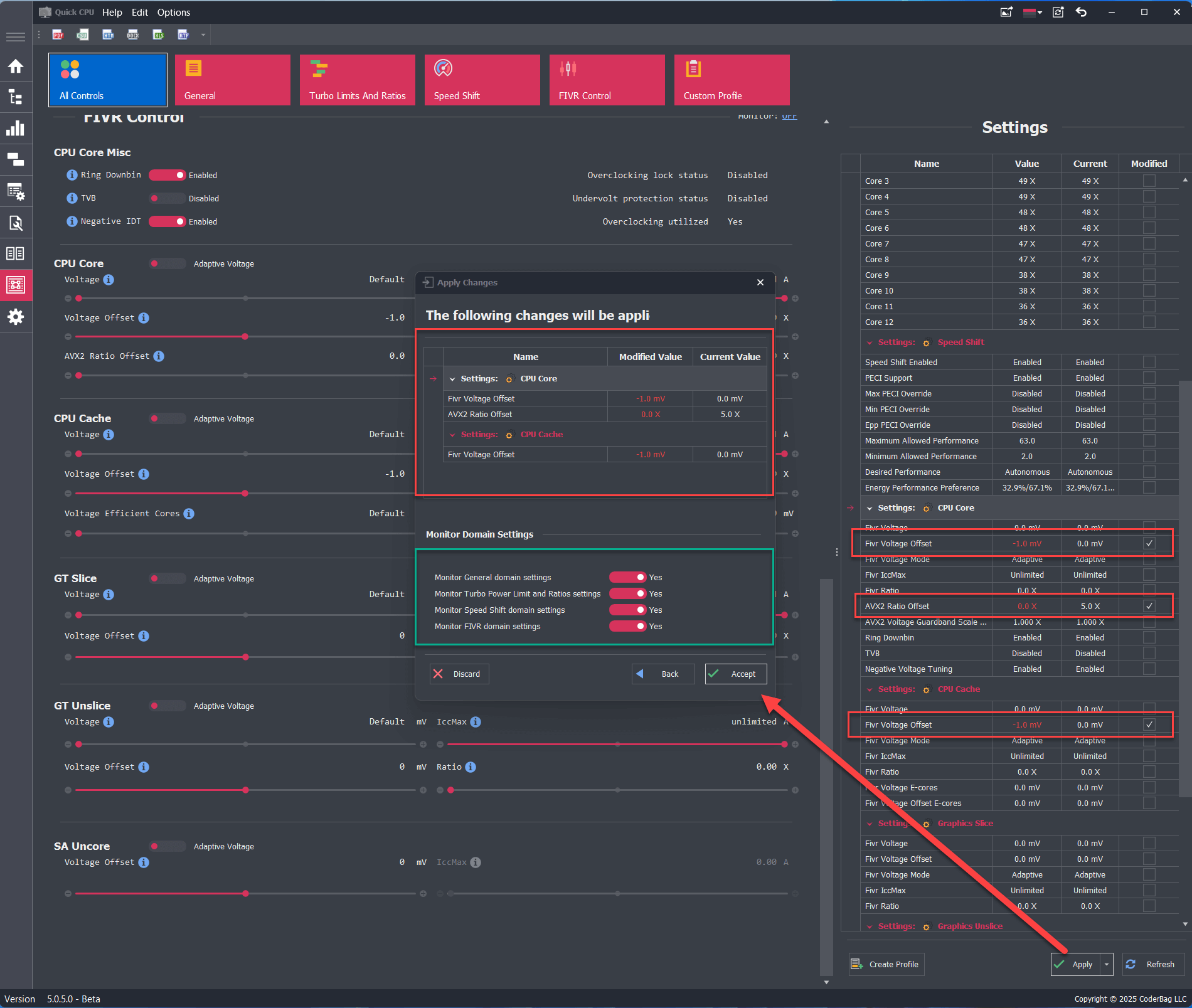
Changes can be applied by clicking the Apply button located on the right-side panel (see section E in the image below). After doing so, an Apply Changes dialog will appear (only if at least one setting was modified). This dialog lists all pending changes and provides options to accept or discard them, as well as to set monitoring preferences.
Monitor Domain Settings
This feature lets you select which domains you want the application to monitor (see image above). If a setting in a domain is modified, the monitoring option is automatically set to Yes and cannot be changed. In the example shown, all domains except the General domain have modified settings, so their monitoring is enforced. Since the General domain has no changes, you may choose whether or not to monitor it.
You can view the monitoring state for each domain next to its name in the interface.
Start/Stop Monitoring Without Modifying Settings
If you haven’t modified any settings but want to change the monitoring status for one or more domains, follow these steps:
- Click the Apply button.
- In the confirmation dialog, click Yes.
- Select your desired monitoring preferences.
- Click Save to apply the monitoring changes.
Accept Changes
When you click the Accept button, all modifications are applied, and monitoring begins for all domains where monitoring is enabled. If another application or the system attempts to modify a monitored setting, Quick CPU will detect the change and try to revert it to the last applied value. In essence, clicking Apply tells Quick CPU to enforce your current configuration. The same applies to Custom Profile settings. Note: The application must remain running (in the system tray or taskbar) to actively monitor your settings.
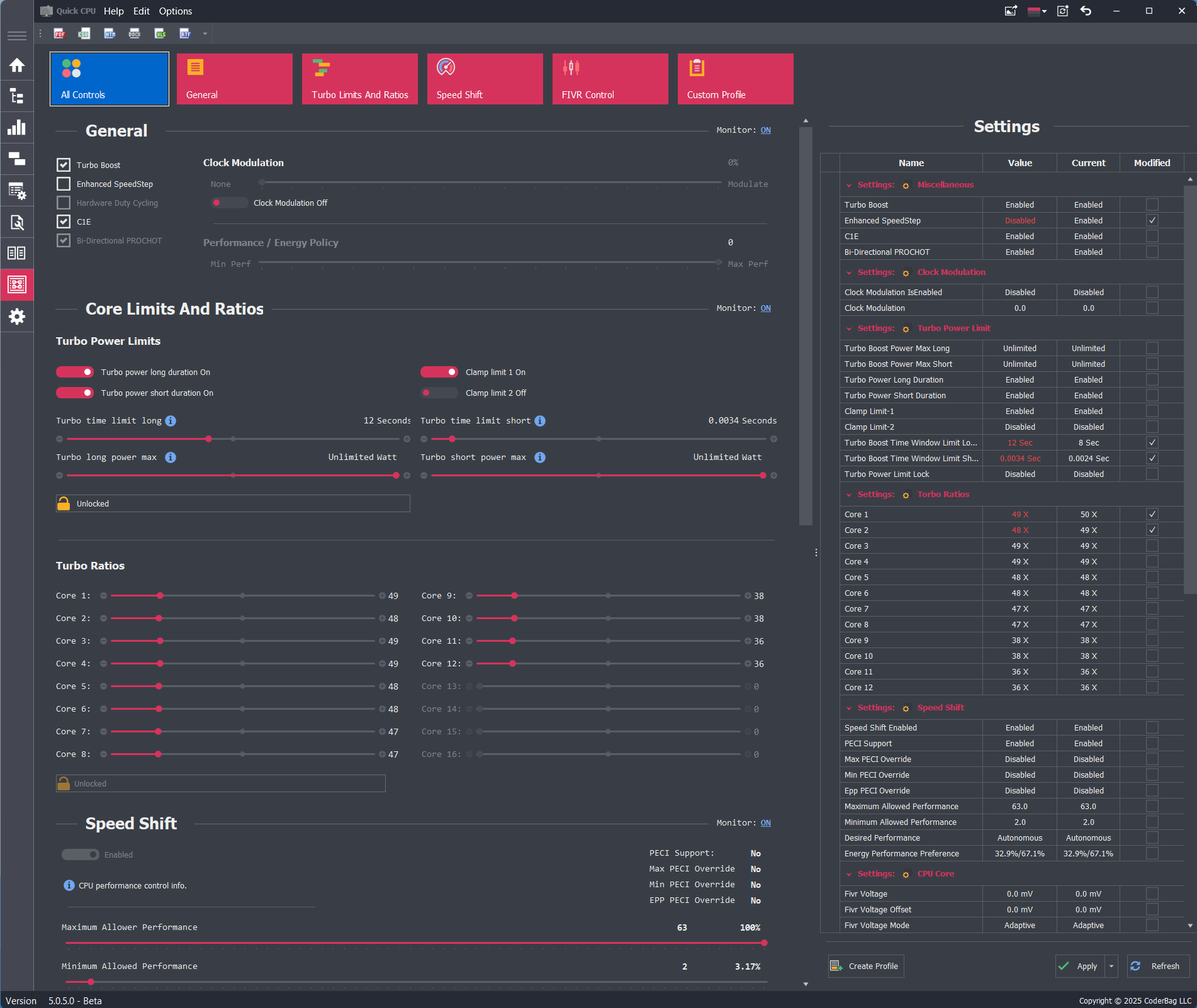
User Interface Details, Features, and Functionality
This section outlines the key UI components of the Advanced CPU Settings dialog.
- Navigation Bar: Navigate between different domain settings.
- Resizable Panel (Vertical & Horizontal): Adjusts the visible space for different areas of the application, such as settings or profile descriptions.
- Grid Column Context Menu: Right-click on a grid column to access UI customization options:
- Sort Ascending: Sorts entries in ascending order based on the selected column.
- Sort Descending: Sorts entries in descending order.
- Hide This Column: Hides the selected column (can be restored via the Column Chooser).
- Column Chooser: Allows selection of hidden columns to display.
- Best Fit: Optimizes column width for content.
- Best Fit (All Columns): Optimizes widths for all grid columns.
- Find Panel: Displays a search panel for quickly locating values.
- Settings Panel: Displays all available settings in a tabular view, grouped by domain. Each setting includes:
- Name: The name of the setting.
- Value: The current control value. If it differs from the applied value, the text color turns red.
- Current: The currently applied setting value.
- Modified: Indicates whether the user has changed the setting value.
- The Settings Panel includes three buttons:
- Create Profile: Saves the current settings as a custom profile. Learn more here.
- Apply: Applies changes to any modified settings. If nothing has changed, this does nothing.
- Refresh: Reloads all settings from the system.
General Settings
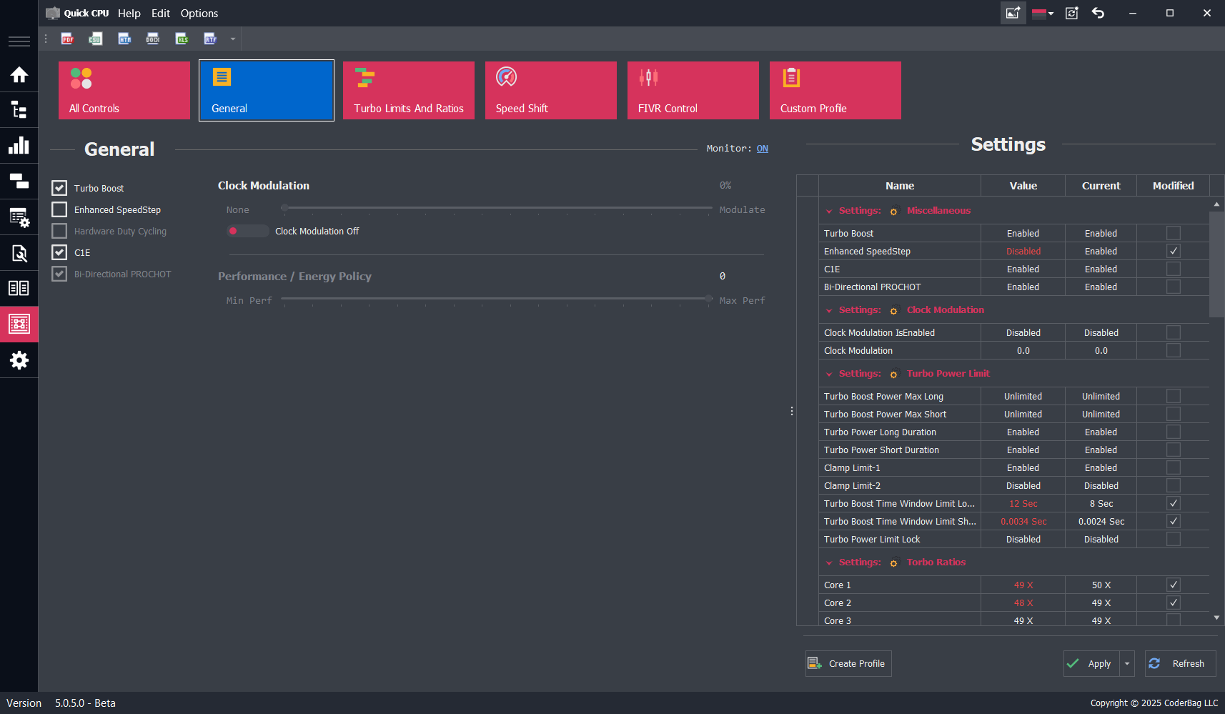
Description
All settings in this section are CPU-dependent and will be enabled or disabled based on your CPU model. The availability of a specific setting may also depend on whether it is locked or unlocked by your system BIOS.
Turbo Boost
If supported by your CPU, this setting allows you to enable (if checked) or disable (if unchecked) Intel Turbo Boost Technology. If power conservation is a priority, unchecking this box will prevent the CPU from entering higher turbo frequency states.
Enhanced SpeedStep
Enhanced Intel SpeedStep® Technology allows the processor to dynamically adjust its voltage and frequency to match workload demands, thereby reducing power consumption and heat generation.
It is an advanced feature that enables high CPU performance while meeting system power-efficiency requirements.
Separation of voltage and frequency changes
Separation of voltage and frequency changes
- By adjusting voltage in smaller steps independently from frequency changes, the processor minimizes system unavailability during transitions. This allows for more frequent state changes and a better balance between performance and power efficiency.
- The bus clock continues running during transitions, even if the core clock and phase-locked loop (PLL) are stopped, allowing critical logic to remain active. The core clock can resume much faster under Enhanced SpeedStep than in older CPU architectures.
C1E
Also known as Enhanced Halt State, C1E is a power-saving feature that reduces power usage when the CPU is idle. When enabled, it allows the processor to transition to the lowest Enhanced SpeedStep operating point when all execution cores enter the C1 (MWAIT) state. Disabling this feature may reduce latency in some systems.
Hardware Duty Cycling (HDC)
Hardware Duty Cycling (HDC) enables the processor to autonomously transition certain components within the CPU package into an idle state during low system activity. For instance, the processor may selectively idle one or more cores and reduce the effective CPU frequency, contributing to overall power savings.
Bi-Directional PROCHOT
When enabled, this feature activates the bi-directional PROCHOT signal. It allows components within the CPU package to signal thermal emergencies and initiate the Thermal Control Circuit (TCC) if the CPU exceeds its maximum thermal threshold.
Clock Modulation
Clock modulation allows implementation of power-saving policies by reducing the duty cycle of the CPU clock. This works in addition to thermal monitoring and power management sensors. Setting a non-zero modulation value reduces the CPU’s effective performance and power consumption.
Performance / Energy Policy
This setting allows the user to select a preference between maximum performance and energy efficiency, influencing how the CPU balances performance and power use.
Turbo Power Limits and Ratios
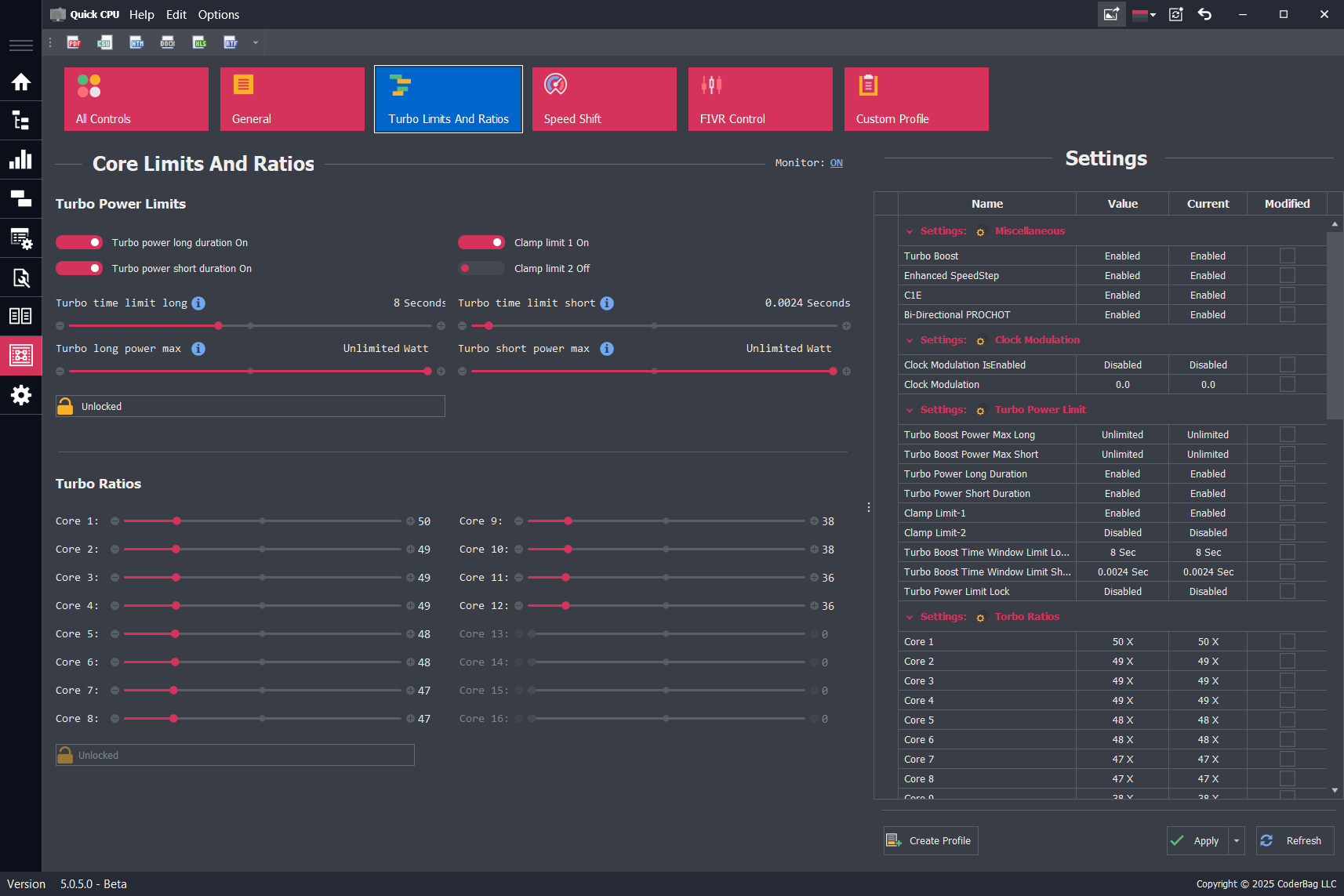
Description
Each Intel processor comes with default specifications that guarantee certain core frequencies within a defined power consumption envelope. The Thermal Design Power (TDP) represents a nominal value for average power consumption based on base clock speeds—not the maximum power draw, especially during turbo operation.
When a processor enters turbo boost mode, power consumption can significantly exceed the specified TDP. In these scenarios, the system's thermal solution becomes critical, determining how long the CPU can sustain elevated frequencies and power levels. Intel defines several programmable power levels to help OEMs and end users tune performance, power efficiency, and thermal behavior according to system design and usage conditions.
Intel Power Levels
This section allows configuration of Turbo Power Limit (TPL) and timing parameters:
- Power Limit Long (PL1): Defines the sustained (long-duration) power limit, typically aligned with TDP. It represents the average power the CPU can draw over a longer period without exceeding thermal limits. Intel recommends aligning PL1 with the capacity of the thermal cooling solution.
- Power Limit Short (PL2): Defines the short-term maximum power the CPU can use for turbo boosts under heavy loads. This is typically set ~25% higher than PL1 by default.
- Clamp Limit 1: When enabled, forces the CPU to strictly adhere to PL1 limits. The processor may drop below requested performance states to remain within power constraints.
- Clamp Limit 2: Functions similarly to Clamp 1 but applies to PL2 enforcement. It restricts short bursts to prevent exceeding short-duration power thresholds.
- Turbo Time Limit Short: Sets the duration (in seconds) that the CPU is allowed to operate in PL2 mode before returning to PL1. This controls how long peak turbo performance is sustained.
- Turbo Short Power Max: Defines the maximum allowable power draw during short-duration turbo operation (PL2).
- Lock/Unlock Control: When locked, all Turbo Power Limit values become read-only and cannot be changed until the next system reboot or deep sleep cycle. This is often used to ensure consistent behavior across restarts.
Note: Even if a time limit is defined, it may be overridden by thermal or current-based throttling mechanisms built into the processor.
Apply Turbo Power Limit settings on application start
To apply Turbo Power Limit settings automatically at application start, create a custom profile with your desired configuration and enable the option to load it on launch. Learn more here: How To Apply Custom Profile Settings On Application Start
NOTE: Once the Lock control is enabled, all Turbo Power Limit settings become static and cannot be modified until the next system reboot or transition to a deep sleep state. If you are using a custom profile that locks TPL settings, ensure that the profile is disabled at startup if you plan to make further modifications.
Turbo Ratios
The Turbo Ratios section allows users to configure CPU frequency multipliers based on the number of active cores. This functionality is available only if the CPU and BIOS allow unlocked ratio control.
- Turbo ratios are specified per core-count—e.g., 1 active core, 2 active cores, up to the total number of cores supported by the CPU.
- Setting a higher multiplier for fewer active cores enables higher boost frequencies in lightly threaded workloads.
- All turbo ratio values must fall within the range allowed by the CPU to ensure stability and compliance with firmware constraints.
Changes to turbo ratios can improve single-core or multi-core performance but may increase power consumption and heat output.
SpeedShift Settings
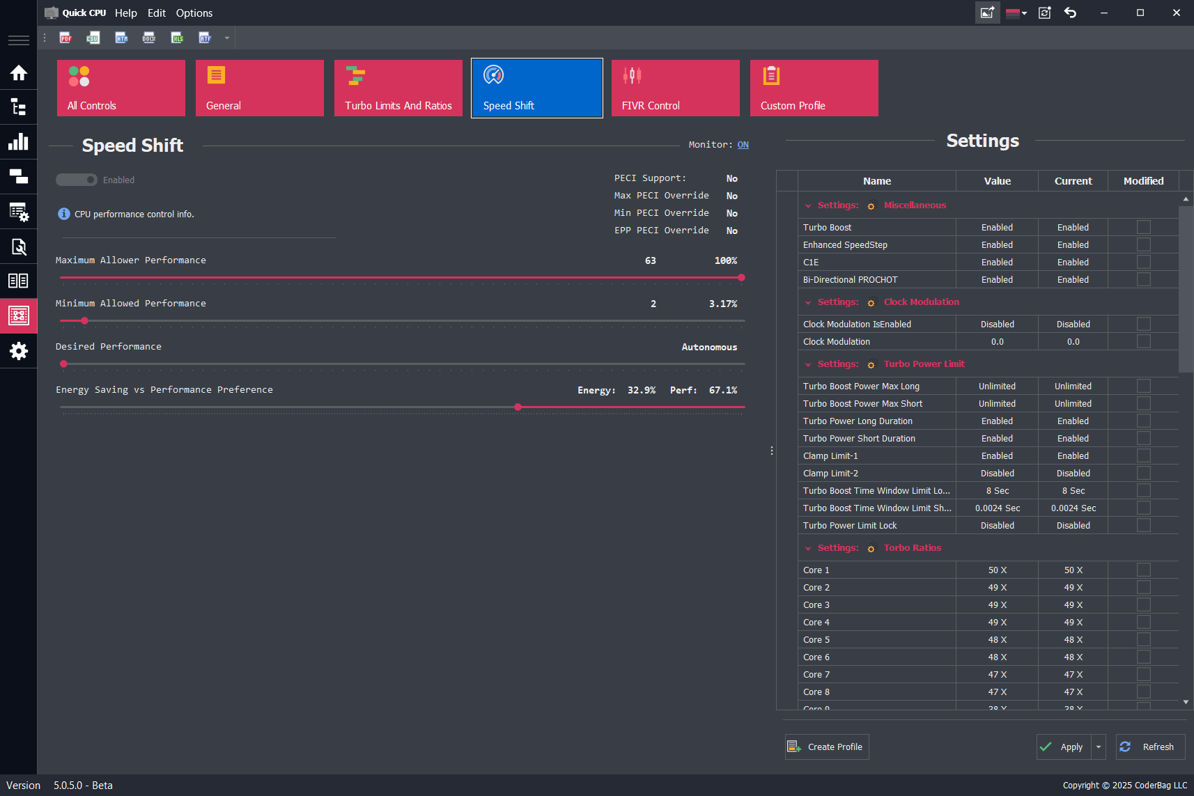
Description
Intel Speed Shift Technology, also known as Hardware-Controlled Performance or HWP (Hardware P-States), is designed to improve CPU responsiveness by allowing the processor to control its own frequency and voltage scaling. This reduces latency when transitioning between power states, resulting in more efficient performance adjustments based on workload demands.
Prior to Speed Shift, performance state changes (P-states) were managed by the operating system. While functional, this approach introduced additional latency. With Speed Shift, introduced in Intel's Skylake architecture, the CPU itself makes real-time decisions about performance scaling, enabling faster and more efficient transitions.
Even with Speed Shift enabled, the processor is still subject to limits imposed by voltage requirements, thermal thresholds, and workload characteristics. This means transitions are faster, but not instantaneous.
Important: On most modern systems, especially those running Windows 10 or 11, Speed Shift is enabled by default and cannot be disabled once active. In these cases, Windows may also override user-defined performance hint values.
Recommendation: It is advised to manage CPU frequency and performance using the system's power management settings (found in the Main or Power Settings controls), or by adjusting Turbo Ratios for more predictable and supported behavior.
Speed Shift Controls
The Speed Shift control panel provides sliders to configure the processor's performance hints. These settings influence how the CPU adjusts its operating frequency in real time.
- Minimum Allowed Performance: Defines the lowest frequency the CPU is allowed to drop to. This is expressed as a performance index rather than MHz or GHz directly.
- Maximum Allowed Performance: Sets the upper limit for CPU frequency. This prevents the CPU from boosting beyond this defined range.
- Desired Performance: Optionally defines a specific performance target. Setting this to
0allows the hardware to choose based on its own logic. A non-zero value gives the CPU a hint toward a specific performance level. - Energy vs. Performance Preference: Sets the balance between power efficiency and performance. Values range from
0(favor performance) to255(favor energy savings).
These sliders allow fine-tuned control over CPU scaling behavior, but their effectiveness may be reduced or overridden by newer operating systems such as Windows 11, which enforces power profiles more aggressively.
Speed Shift Levels of Control
Intel Speed Shift supports various levels of performance hint control, prioritized as follows:
- PECI: Platform Environment Control Interface. If available, PECI has the highest priority and can override all other settings. Most consumer systems do not support PECI-based Speed Shift control.
- Core Level: Applies performance hints per CPU core. This level takes precedence over package-level control and is most commonly used.
- Package Level: Applies hints at the entire CPU package level. Used when per-core control is unavailable or unsupported.
FIVR Control Settings
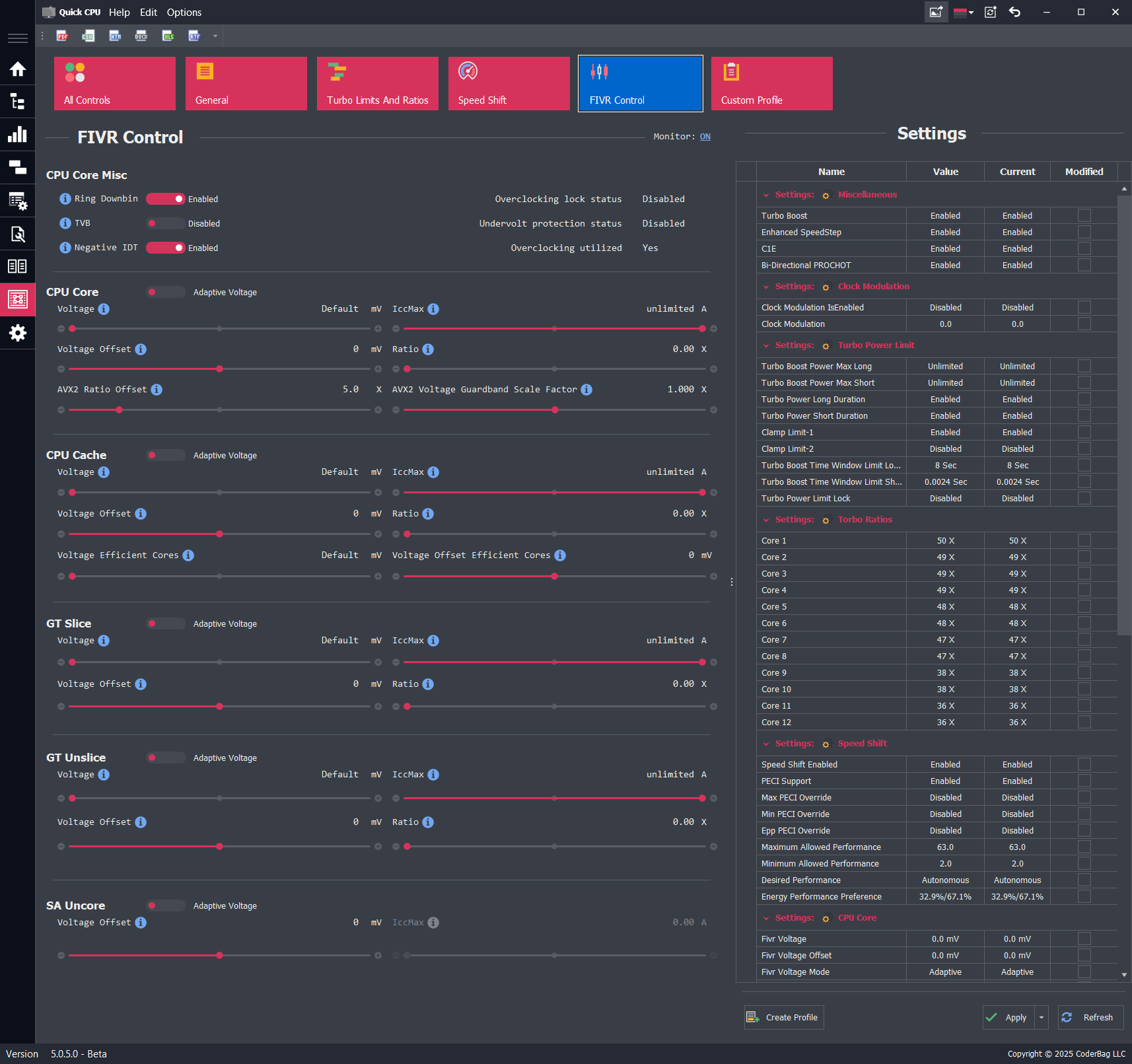
Intel Fully Integrated Voltage Regulator (FIVR) Controls
Description
The FIVR Control panel in Quick CPU allows users to directly modify supported voltage, frequency, and current limit parameters exposed by Intel’s Fully Integrated Voltage Regulator. These settings are fully editable (not monitoring only) and can be changed through Quick CPU as long as the CPU model and system firmware permit access.
Depending on the platform, Quick CPU provides adjustable controls for voltage, adaptive voltage behavior, frequency ratios, BCLK Frequency, AVX offsets, IccMax limits, and other FIVR domain-specific parameters. If features are restricted by BIOS or microcode, the corresponding controls may be locked or read-only.
NOTE: Undervolting is generally safe, but excessive reduction may cause system instability. Overvolting can permanently damage the processor. Make small, incremental adjustments and test system stability after each change.
FIVR Domains and Settings
CPU Core
- Ring Downbin: Enables or disables the offset between ring (uncore) and core frequencies. Enabled: Ring runs at a lower frequency than core. Disabled: Ring and core run at the same frequency.
- Thermal Velocity Boost (TVB): Dynamically adjusts processor frequency based on temperature. Enabled: Higher frequency at lower temps. Disabled: Disables temperature-based frequency boost, but general thermal throttling still applies.
- Negative IDT: Temperature-based voltage reduction tied to TVB. Enabled: Voltage is lowered based on temperature. Disabled: Runs at fixed voltage regardless of thermal conditions.
- Adaptive Voltage: Determines how voltage is automatically adjusted based on load.
- Voltage: Sets the base voltage supplied to CPU cores.
- Voltage Offset: Applies a constant positive or negative offset to the requested core voltage.
- IccMax: Maximum current the core voltage rail can deliver. Raising this can reduce current throttling.
- Ratio: Overclocking multiplier for frequency-to-voltage mapping.
- AVX2 Ratio Offset: Reduces effective core multiplier during AVX2 workloads to manage thermals.
- AVX512 Ratio Offset: Same as above but for AVX512 workloads.
- AVX2/AVX512 Voltage Guardband Scale Factor: Scales voltage guardbands to adjust safety margins during AVX workload execution.
- BCLK Frequency (Reference Clock): This is the base reference clock (BCLK). On most platforms, it drives the CPU cores, Ring, System Agent, memory, and integrated graphics. On newer platforms with a separate SoC reference clock, this setting primarily affects CPU cores and Ring, while memory, fabric, and NPU are derived from the SoC clock.
- SOC Frequency: This is the dedicated SOC reference clock. It provides the base frequency for Memory, System Fabric, NPU, and other SOC-level components. On platforms with separate SOC and CPU reference clocks, this setting does not affect CPU cores or Ring frequency, which are instead derived from the CPU BCLK.
CPU Cache
- Adaptive Voltage: Determines how the cache voltage is regulated under load.
- Voltage: Sets the base voltage for the cache interface.
- Voltage Offset: Applies a constant voltage adjustment to the cache.
- IccMax: Maximum allowable current for the cache power rail.
- Ratio: Sets the maximum frequency for the cache interface.
- Voltage Efficient Cores: Voltage level for the Efficient Cores’ cache interface.
- Voltage Offset Efficient Cores: Applies an offset to the Efficient Cores cache voltage.
GT Slice (Integrated Graphics)
- Adaptive Voltage: Regulates graphics voltage behavior.
- Voltage: Base voltage for graphics cores.
- Voltage Offset: Constant adjustment to graphics voltage.
- IccMax: Maximum current for the GT voltage rail.
- Ratio: Multiplier for maximum GPU frequency (in combination with base clock).
GT Unslice (Graphics Media)
- Adaptive Voltage: Voltage regulation behavior for GT media engine.
- Voltage: Voltage supplied to media/unslice domain.
- Voltage Offset: Offset applied to media voltage.
- IccMax: Max current draw for the graphics media domain.
- Ratio: Frequency multiplier for GT Unslice (media engine).
SA Uncore (System Agent)
- Adaptive Voltage: Governs automatic voltage behavior for the System Agent.
- Voltage Offset: Voltage adjustment applied to the SA.
- IccMax: Maximum allowable current for the System Agent voltage rail.
SA Fabric / Next Generation Uncore (NGU)
- Adaptive Voltage: Selects the algorithm used to control the SA Fabric or Next Generation Uncore (NGU) voltage.
- Voltage: Voltage Override for SA Fabric or Next Generation Uncore (NGU). SA Fabric shares voltage rails with other domains that cannot be controlled, therefore lowering this value will not always be reflected in actual voltage delivered.
- Voltage Offset: This offset is applied to the requested SA Fabric voltage at all times. SA Fabric shares voltage rails with other domain that cannot be controlled, therefore lowering this value will not always be reflected in actual voltage delivered.
- Ratio: Requested operating frequency of the SA Fabric or Next Generation Uncore (NGU).
Undervolting Guidance
Each CPU has factory-calibrated voltage margins that ensure stability under a variety of workloads. Through undervolting (negative voltage offset), users attempt to reduce power consumption and heat without compromising stability.
The optimal undervolt value varies across chips—even among the same CPU models—due to manufacturing variation. If undervolted too far, the system may crash or freeze. It's recommended to gradually reduce voltage and test stability under both idle and load conditions.
Overvolting Notes
Overvolting can be performed by increasing the voltage offset or directly setting a higher static voltage. While offset-based overvolting can scale dynamically, setting a fixed higher voltage applies at all times and may significantly increase heat and power usage.
Adjusting IccMax
Raising IccMax increases the current limit available to a voltage domain. This may help avoid power delivery throttling during high-load conditions, especially when overclocking.
Apply FIVR Settings at Startup
To apply FIVR settings automatically on application launch, create and save a custom profile that includes your voltage and current modifications. Then configure the application to load this profile on startup.
Learn more: How To Apply Custom Profile Settings On Application Start
Important: FIVR controls may be fully editable, partially available, or locked depending on your CPU generation, OEM firmware settings, and platform security policies. Quick CPU will only allow modification of settings that your hardware officially supports and exposes.
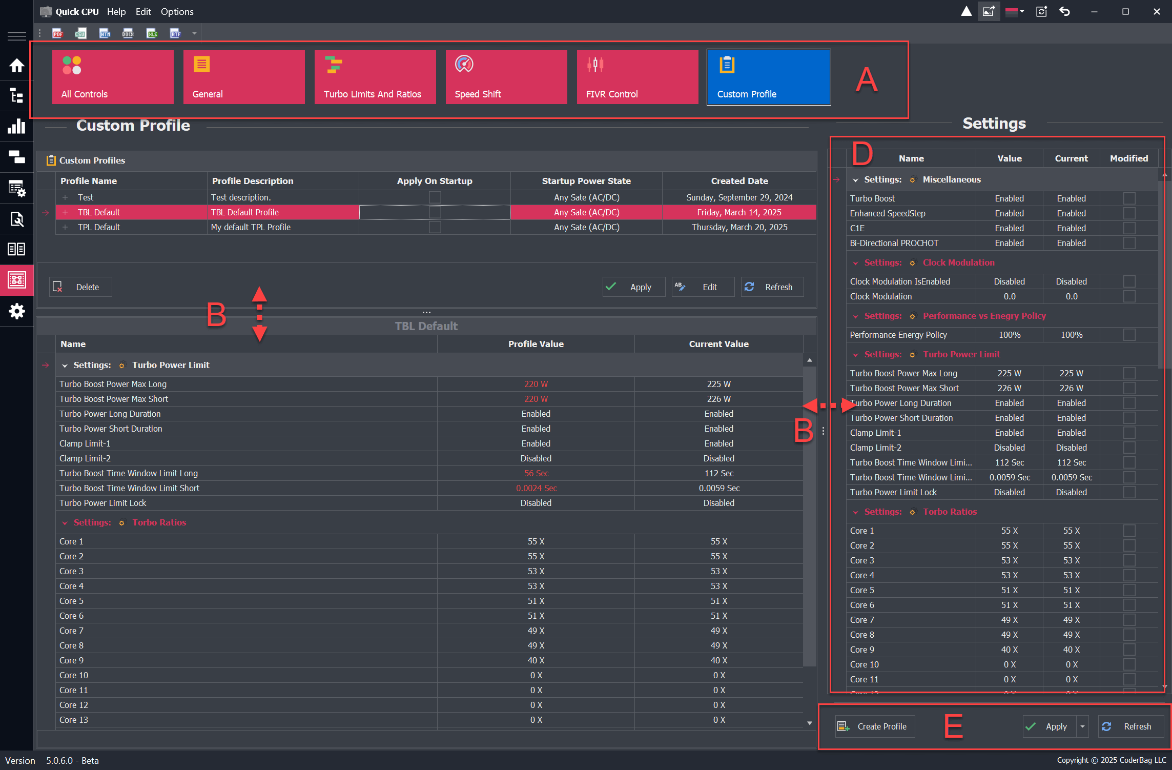
Custom Profile Settings
Description
This functionality allows you to create one or more Custom Setting Profiles. These user-defined profiles include a subset of settings supported by your processor and can be tailored to specific scenarios or workloads. Once created, they can be applied as needed.
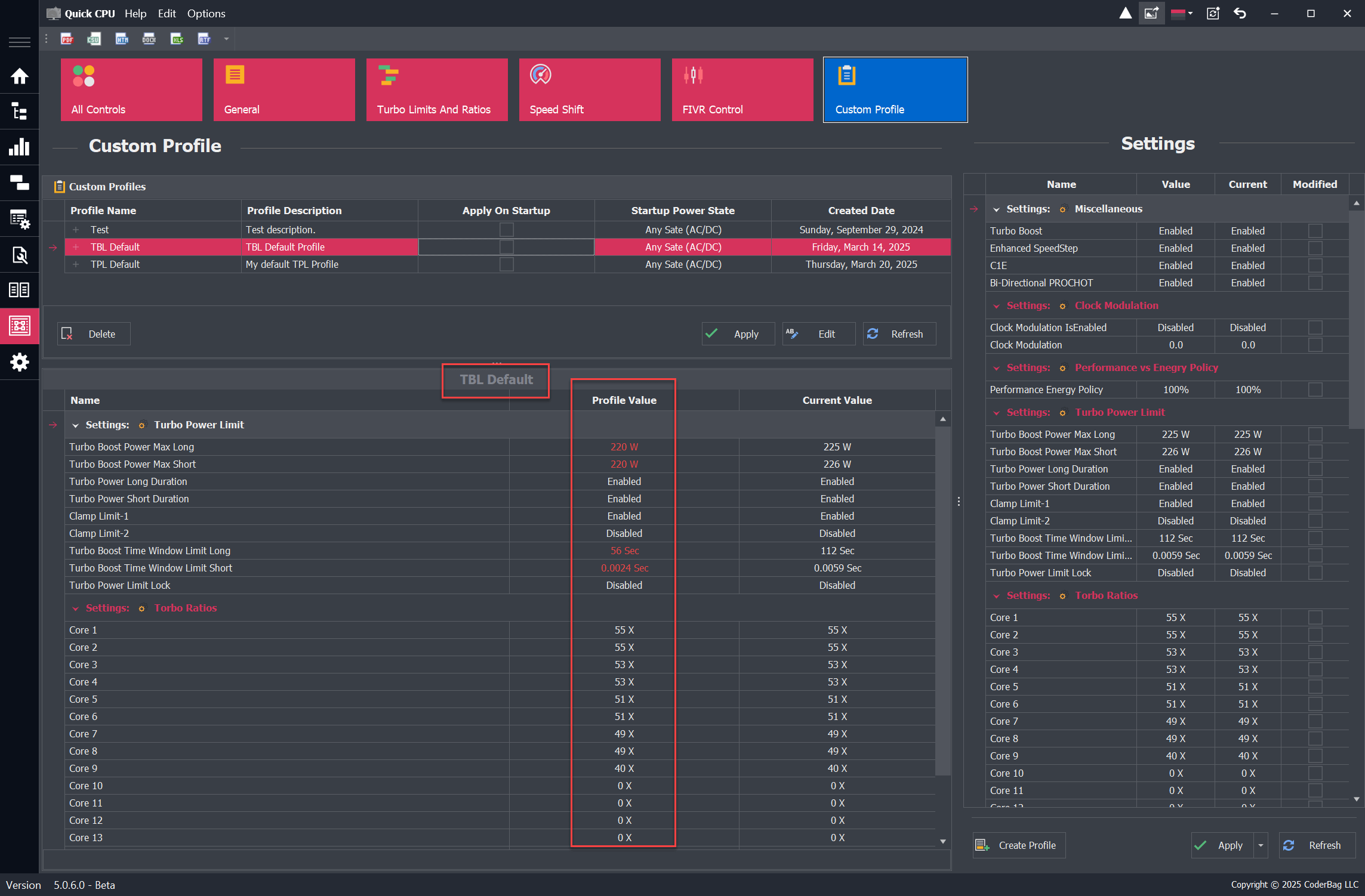
Profile View Layout
The Custom Profile view is divided into two main sections:
- Top Section: Displays a list of previously saved profiles. Each column represents the attributes selected during profile creation.
- Bottom Section: Shows all settings related to the selected profile, including the profile name and details.
How to Create or Edit a Custom Profile
Create Custom Profile
To create a new profile, click the Create Profile button in the Settings section. A dialog will appear where you can configure the profile. Some fields are mandatory, while others are optional.
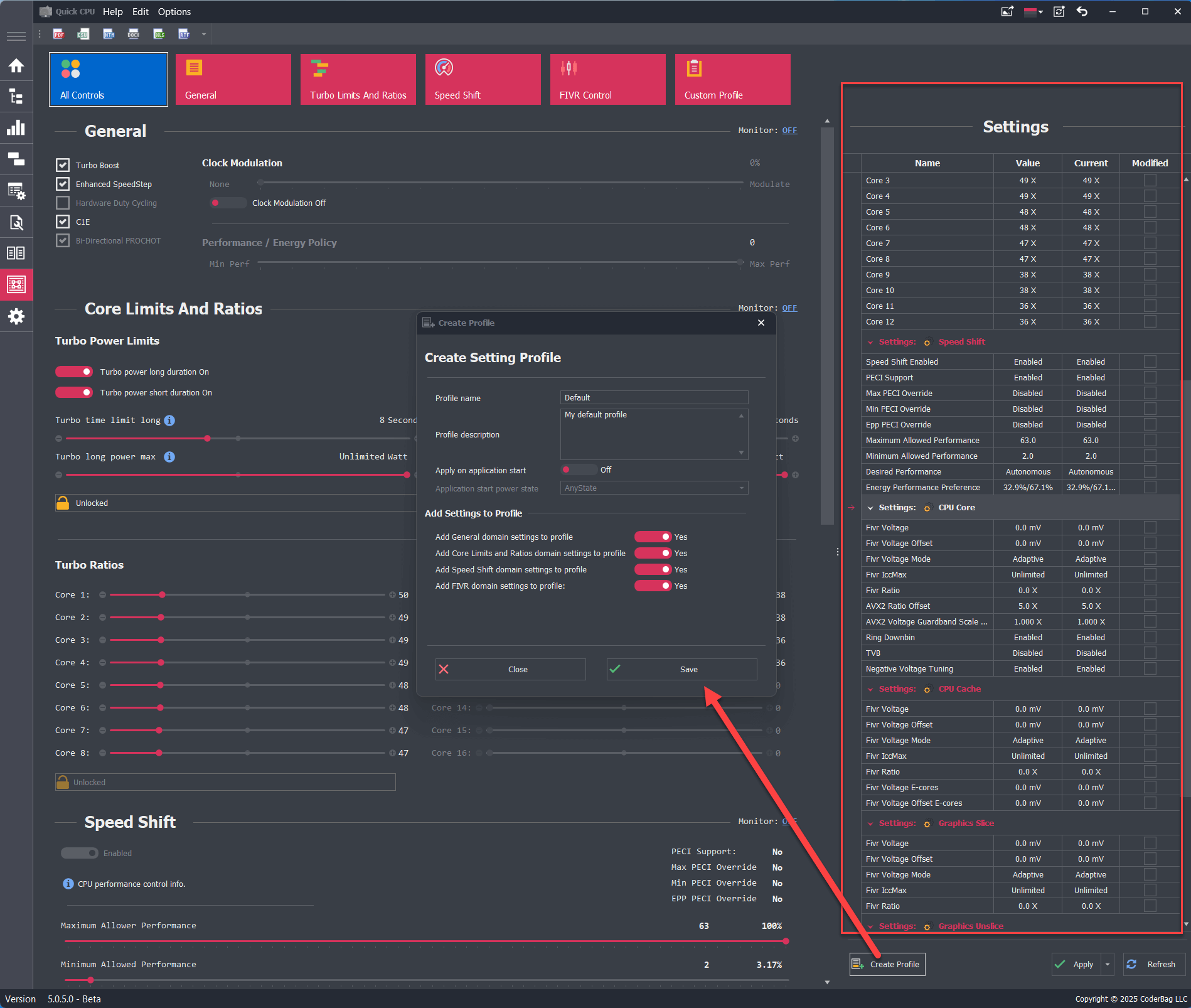
- Profile Name: Required field that specifies the name of the profile.
- Profile Description: Optional field for a descriptive label.
- Apply on Application Start: Required toggle (default: OFF) that determines if the profile is auto-applied on app start.
- Application Start Power State: Available only if the above is ON. Specifies when to load the profile:
- Any State: Default, applies regardless of power source (recommended for desktops).
- Plugged In: Applies only when on AC power.
- On Battery: Applies only when on battery power.
- Add Settings to Profile: At least one domain must be included. Disabled domains cannot be selected.
Example: To create a Speed Shift-only profile:- Monitor General domain: No
- Monitor Turbo Power Limits and Ratios: No
- Monitor Speed Shift domain: Yes
- Monitor FIVR domain: No
After creation, the profile appears under the Custom Profiles section and includes the active settings at that time.
Edit Custom Profile
To edit a profile, select it and click the Edit button. You can change the name, description, startup toggle, and power state option.
Note: You cannot edit the actual setting values within an existing profile. To do that, either delete and recreate the profile, or create a new one with the desired settings.
Apply Settings from a Selected Profile
To apply a profile, select it and click Apply. A dialog will list all the changes that will be made.
Note: If the current system settings already match the selected profile, no changes will occur.
How to Apply Custom Profile Settings on Application Start
There are two ways to set a profile to auto-apply when the application starts:
Option 1: Create a New Auto-Applied Profile
- Modify one or more settings.
- Click Apply.
- Click Create Profile.
- Enter a profile name and select domains.
- Enable Apply on Application Start.
- Select Any State as the Power State.
- Click Save.
- Quick CPU will now apply this profile each time it starts.
Option 2: Use an Existing Profile
- Go to the Custom Profile tab.
- Select your preferred profile.
- Click Edit.
- Enable Apply on Application Start.
- Select a Power State (Any State if unsure).
- Click Save.
Apply Profile on System Startup
To apply your custom profile on system boot:
- In the main Quick CPU window, go to Options.
- Select "Start application on system startup".
- To start minimized, also enable "Start in system tray".
About Our Software
Enhance and monitor system performance, customize favorite settings and more…


